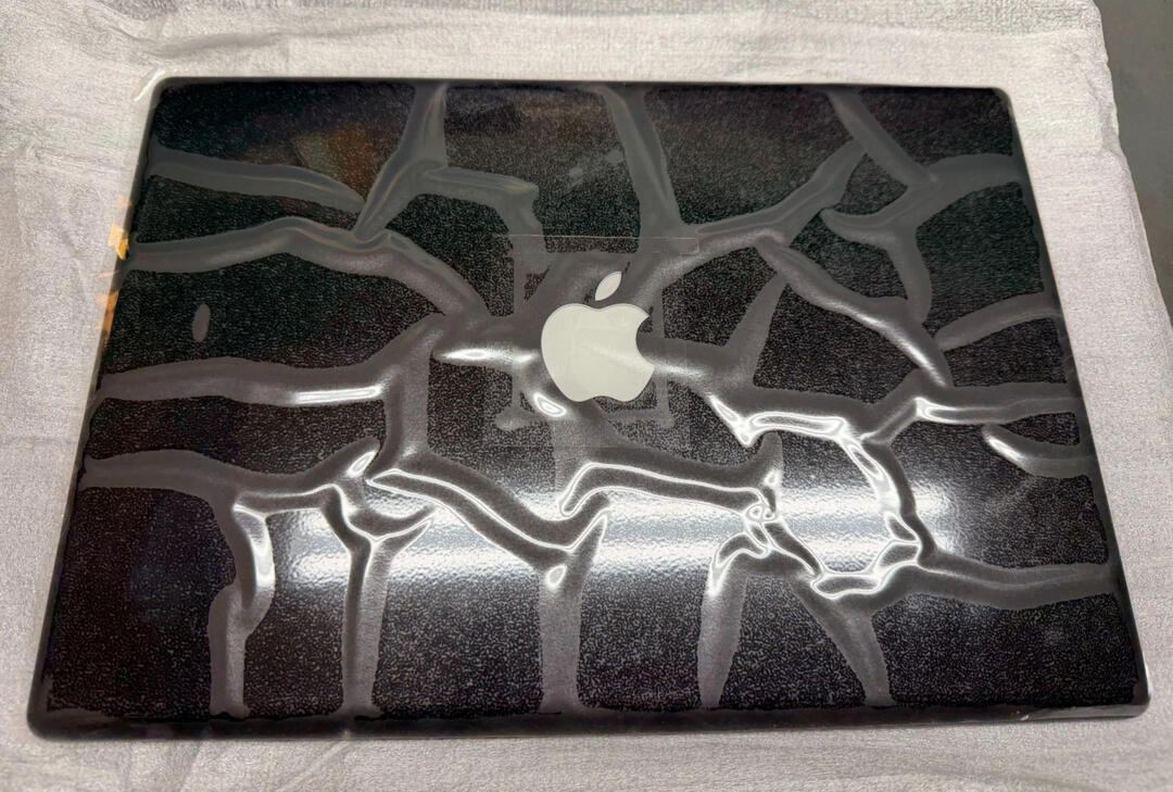
FrameBook.
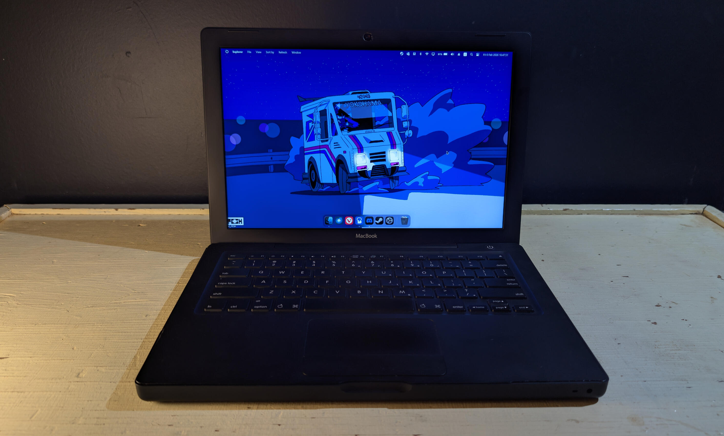
wallpaper credit: @TY-PESH
A reimagined classic, that's only a little bit janky.
the first-gen macbook from '06 is one of my favorite laptop designs ever, mostly because for the longest time it was one of the only macbooks u could get in black besides the powerbook g3.plus it was the first macbook i ever personally owned, although this was around 2015, so even by then the performance was pretty crummy.what inspired me to do this project was reading articles and watching videos about people retrofitting old macs and old pcs with new guts (usually m1 minis), and i got really motivated when i read that someone had already done something like this, and after watching f4mi's video on converting an imac g5 to a fully-kitted monitor.
and so, after doing lots of research into motherboards, display panels, and gathering everything i could think i would need for this project, in the wise words of NileRed:
i decided to just go for it.
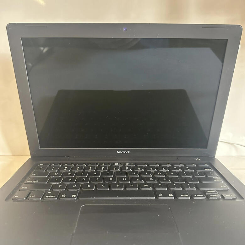
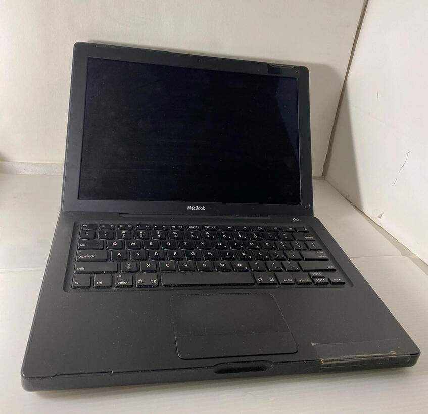
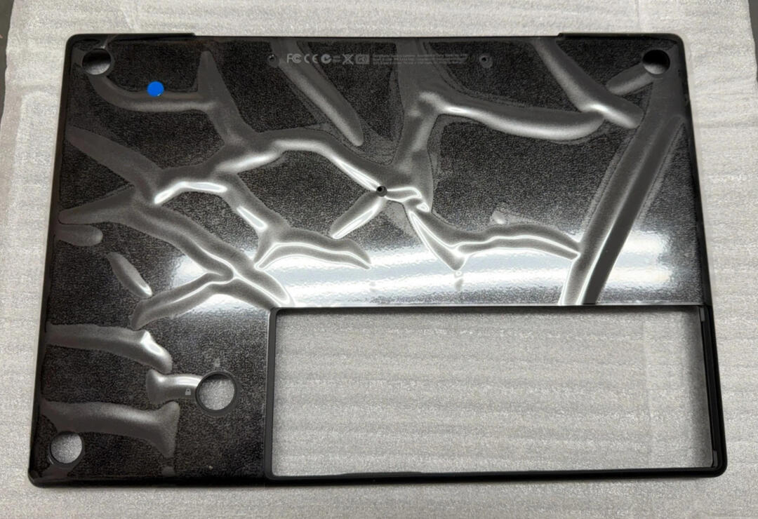
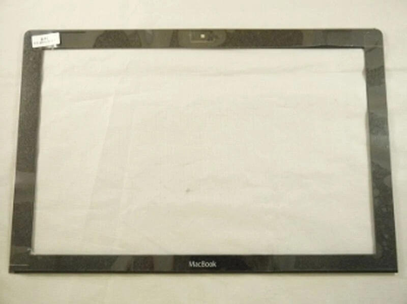
to begin, i ordered a few black polycarb macbooks (model a1181) from ebay. they were all pretty beat up and didn't have their batteries, nor did they power on.i then found and order some oem parts of the outer chassis that i guess had never been made into an actual uniti then follow an ifixit tutorial to completely take apart the macbooks, till i was down to just the bare chassis. my main idea was that the used macs were gonna be my test runs before i did anything with the oem parts, since they were the cleanest looking parts.pretty much all of the parts of the mac i discarded, since they didn't work and even on their own, aren't worth alot if i did sell them. i did keep only a few metal brackets that screwed into the bottom of the bottom chassis (after dremeling away the "middle" section for the old removeable ram sticks), and another that's screwed in at the top that actually holds the hinges for the top chassis.
here's the guts i'm putting in the macbook:
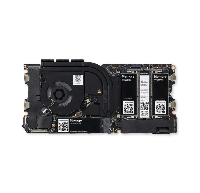
Framework Laptop 13 Mainboard - Intel® Core™ i7-1280P
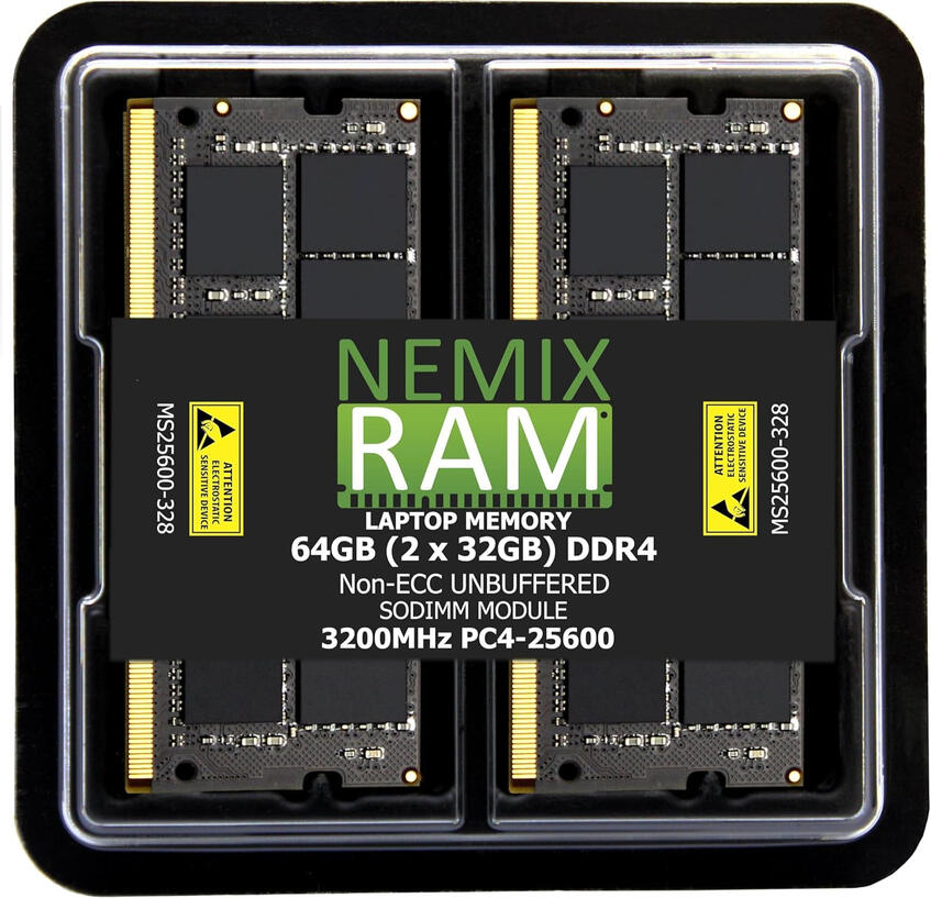
64GB 2X32GB DDR4 RAM
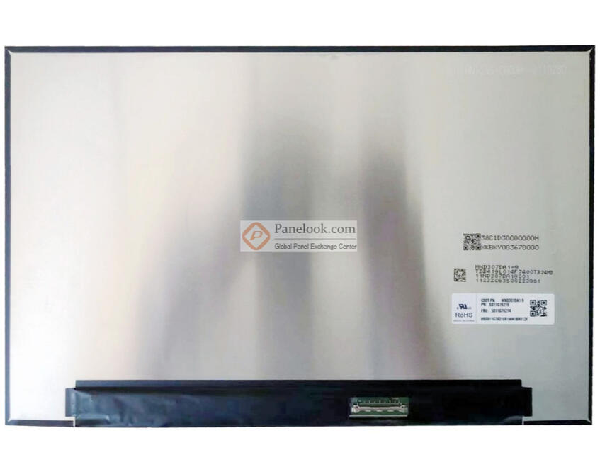
MND307DA1-9 CSOT Display Panel
and here's some periperals and other things i put in the mac
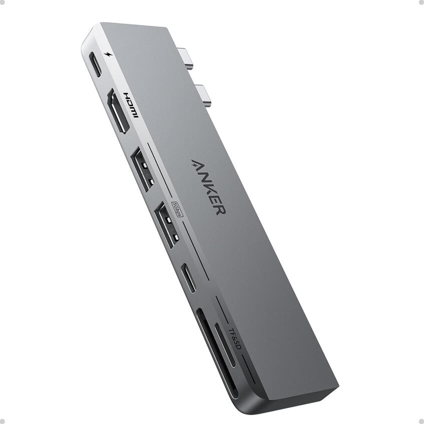
Anker USB C Hub, 7-in-2
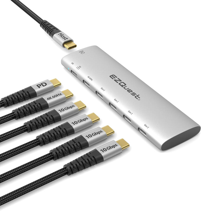
EZQuest USB-C Hub, 6-in-1
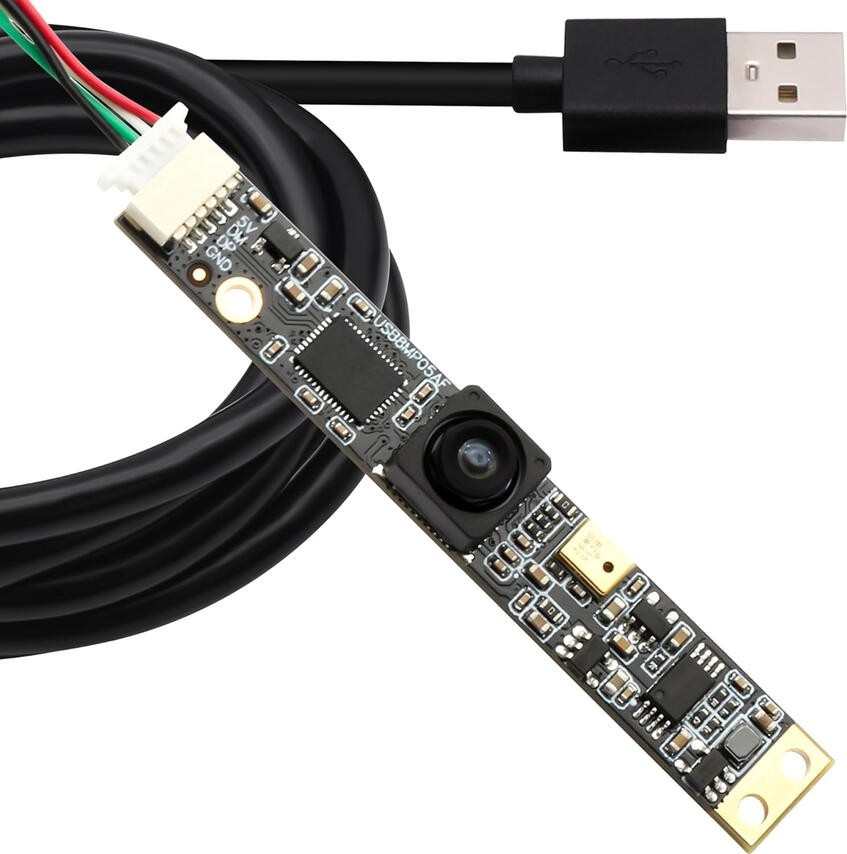
SVPRO 8MP USB Camera
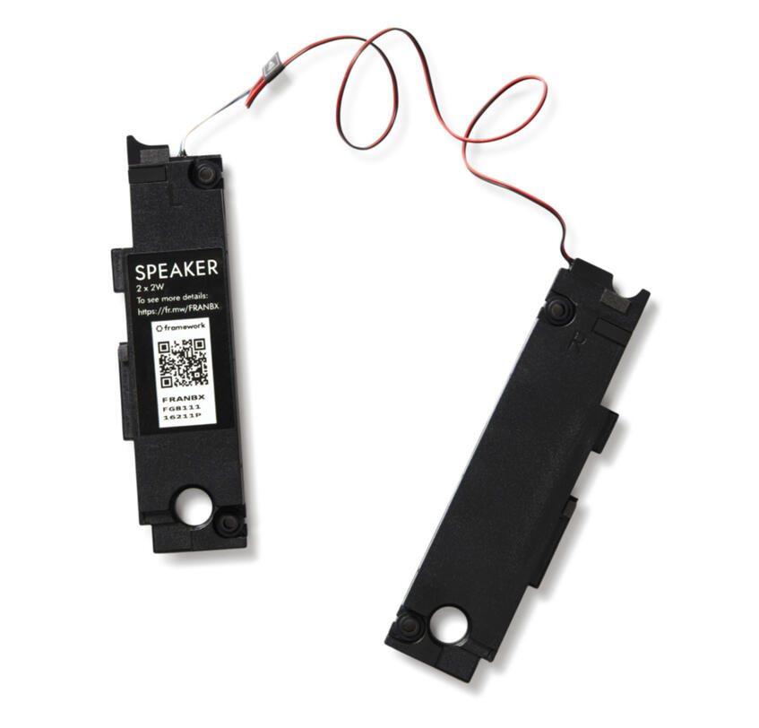
Framework Laptop 13 Speaker Kit
USB 2.0 Expansion Module
and away we go...
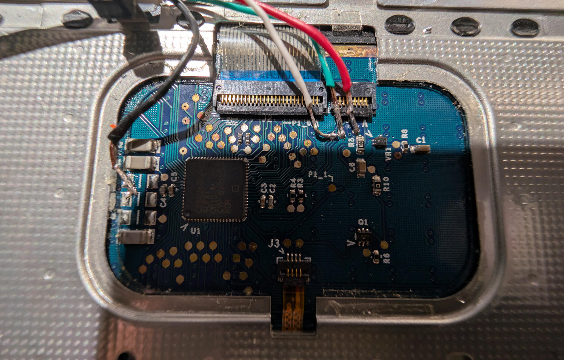
my first concern was if i could use the top case, or the Apple Internal Keyboard/Trackpad. fortunately i found an article that allows you to tap into the case's circuitry and solder a usb cable to use it as a keyboard and trackpad for pretty much everywhere.so, this was actually the very first time soldered anything ever lol. i had watched plenty of soldering videos and stuff so i felt pretty confident, and when i finished soldering on a usb-c and plugged it into my main computer, it actually worked!as a side note, the solder pads are quite small and fragile, i learned the hard way by accidentally yanking the cable and tearing the solder pads off the case's pcb. :|so i got a new top case and soldered a new cable again.
to start putting the macbook together, i removed the original brass insert standoffs from the bottom case and replaced them with my own 3d printed standoffs.for my standoffs i just used gorilla glue to hold them in place, not super ideal, but idk much about welding plastics together and stuff like that so; super glue ftw lol.i reused the original screws used throughout the mac since they were all the same thickness - M2 size - and i started to slowly piece together where i was going to put everything.
come on in !

here's an early picture i took where i figured out where to put most things. the mainboard i put slightly offcentered in the middle, mostly cause i wanted to center the fan's exhaust out the back the best it could. there is a beam in the middle of the exhaust for a screw to go in at the bottom of the mac, but i figured it'd be ok.i mounted the speakers in the most obvious spots, they sound, fine. maybe a little better than the original macbook's speakers.i also seperately got an original dead macbook battery that matched the laptop, and very, very carefully, removed the plastic side that held in the battery cells and just super glued it to the backside of the chassis to fill in the giant hole, since i had no real desire or way of use the removable batteries with the mainboard, since the internal connectors for both framework's battery and apple's battery are completely different.i also 3d printed a custom made "button" to fill in the hole left by the missing locking mechanism for the og battery.
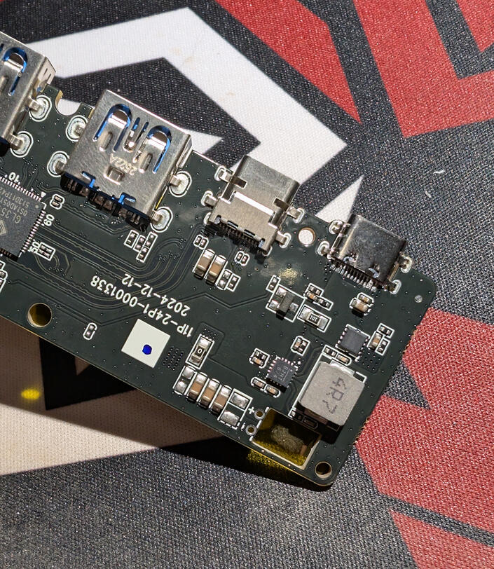
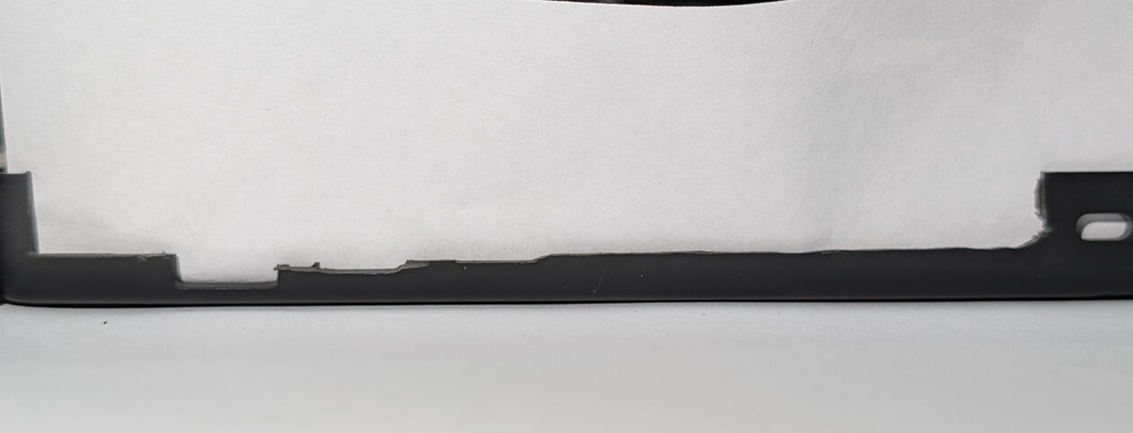
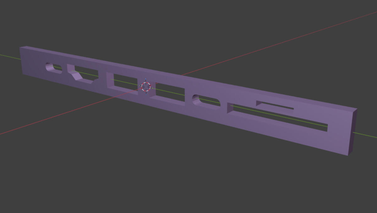
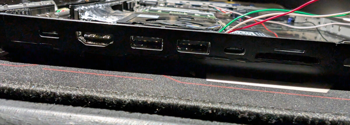
one of the trickest parts of the whole project was figuring out what to do with the I/O, namely the left side of the chassis, since that's where all of the original ports were housed directly on the original logic board of the macbook.taking inspiration from the f4mi video from before, i ordered some usb hubs, stripped them out of their enclosures, and 3d printed some custom standoffs that allow them to be mounted in a way that holds them in place, while allowing me to easily remove them with screws.i also worked quite hard on modeling an "I/O shield" for the left side since i didn't want to try to work around the old holes for the original ports, so i dremeled that side out, took a scan of the aftermath, and meticulously remade the side of the chassis to perfectly fit the hubs' new ports.i then just super glued the shield onto the chassis, again, not super ideal, but it does hold up quite well!
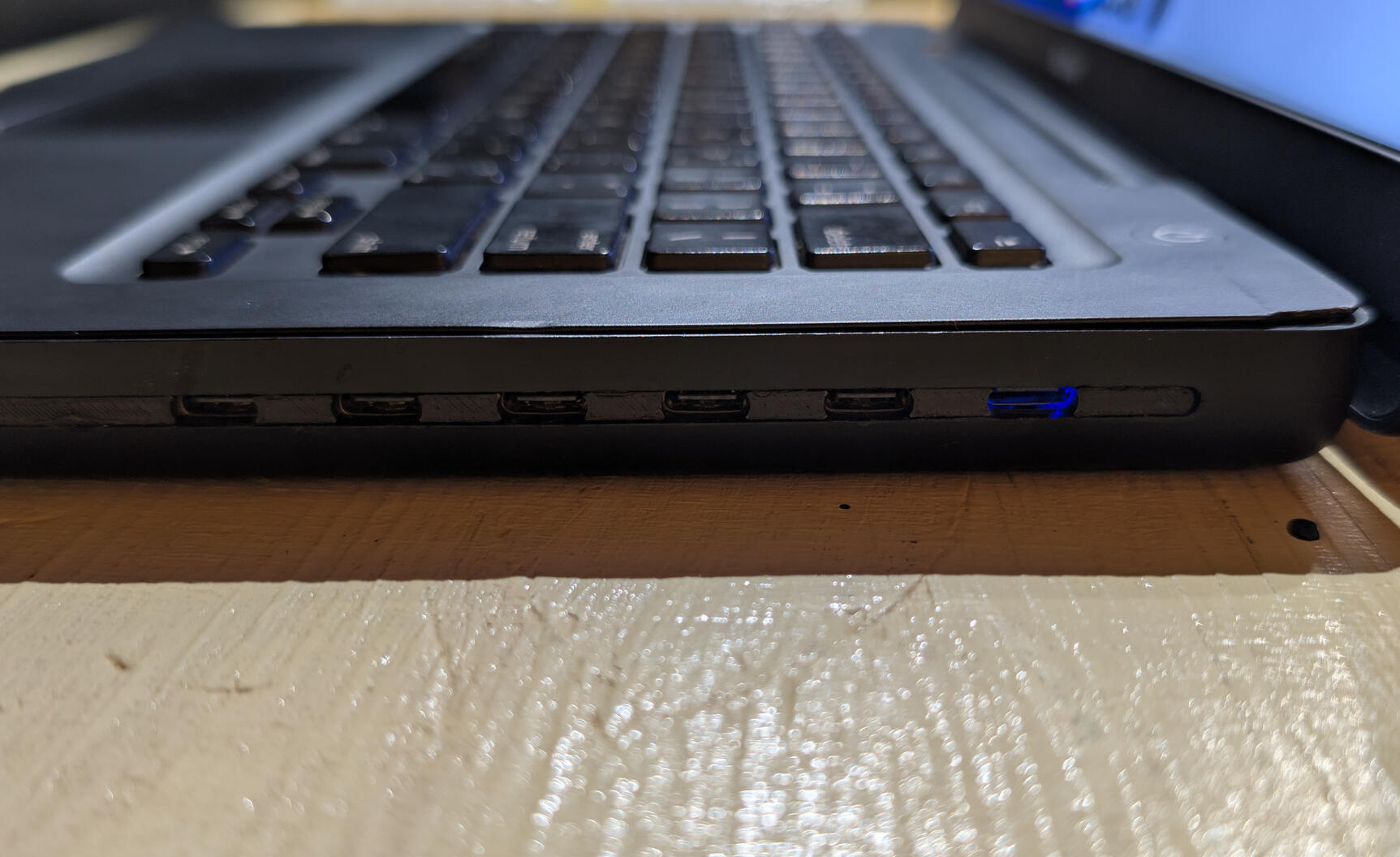
the right side was thankfully much easier than the left, since the old dvd drive's slot was exactly the height of a usb c port. so i order a usb c hub, design a shield to fill in the gaps between the ports, and mounted it will some standoffs.better yet, this side has a mounting piece that not only holds down the ports and prevents from lifting up, it also clips the top case down.
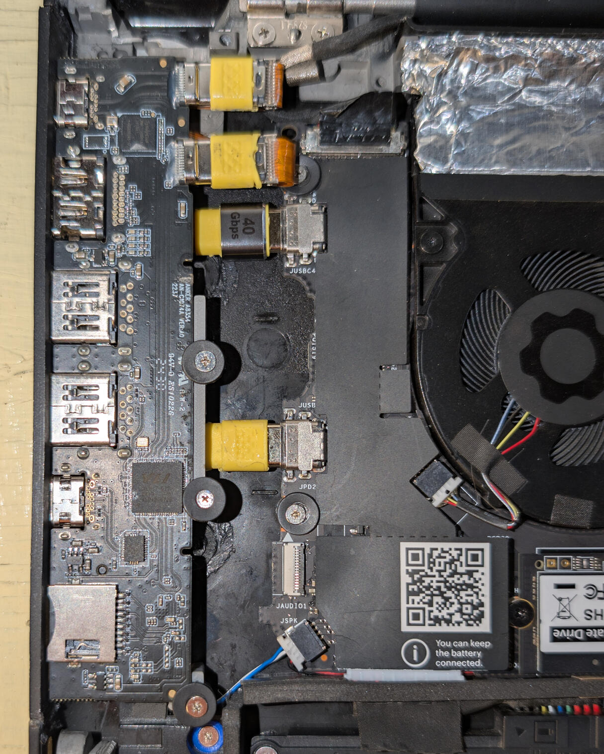
to connect the hubs to the mainboard, i used some small flat usb c cables and stripped them of their rubber coating to expose their fpc cables, did some folds to clean up the slack, and connected them.to connect the top case and the webcam to the mainboard, i ended up getting this small usb module on the right that i soldered the connections to, which then feeds into this input shim that breaks out the connector into solderable points.the power button for the top case is a similar story, where i carefully removed the original membrane button and replaced it with a small button that breaks out into to header pins. those pins then plug into two wires that run to the same input shim to turn the mainboard on.
it's alive !
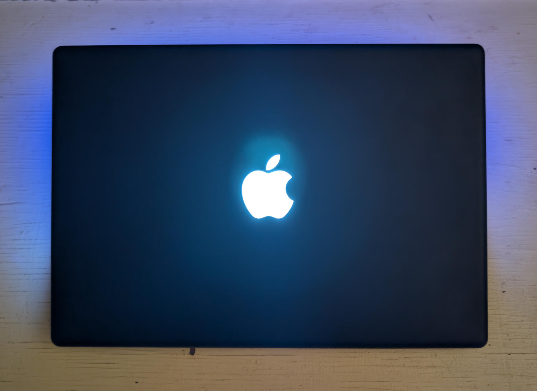
now this wouldn't be a macbook without the classic glowing apple logo on the back. and at first, i really didn't know how to replicate the glowing logo.
the original display panel of the macbook was designed to allow the backlight of the panel itself to double as the backlight of the display, and as the light to shine through the logo, thus allowing the logo to glow. u can actually see the logo through the display if u have a black image over where the logo is.
my best idea was to find a panel thin enough to fit an led of some kind to turn on when the system is on.
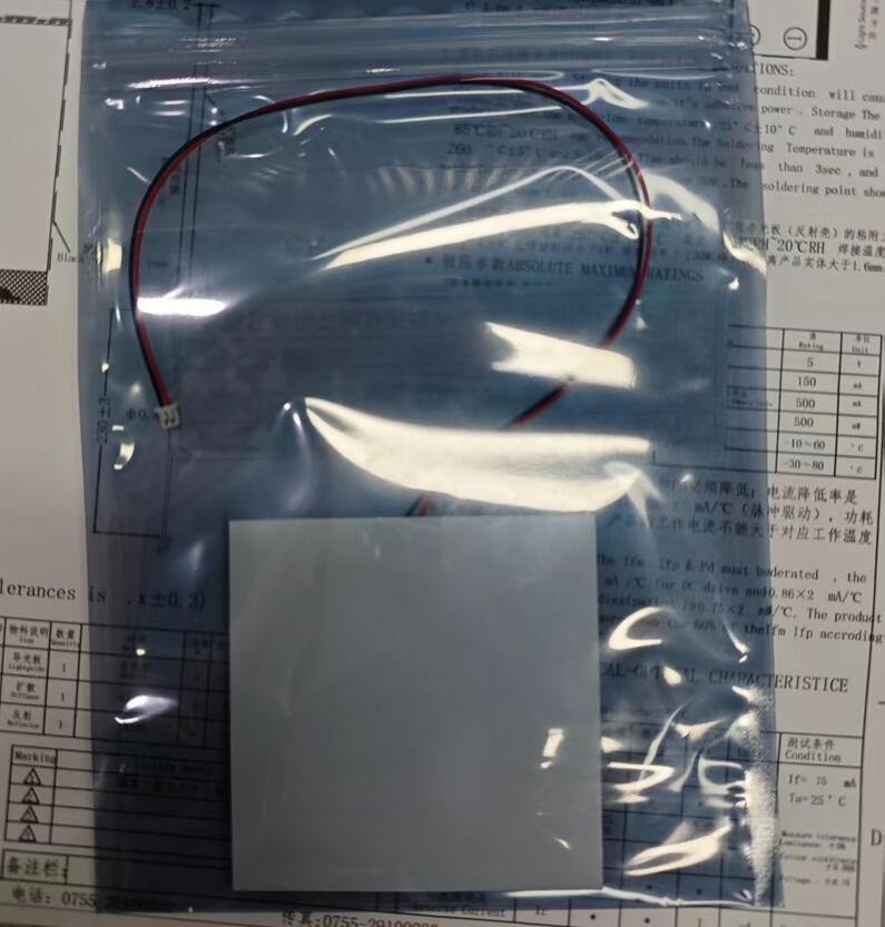
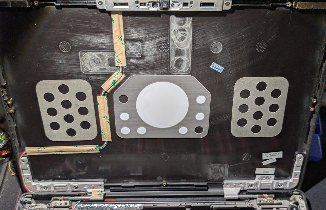
after searching on alibaba and talking with a seller, i ordered a custom made 7x7x0.28 cm led that i mounted (aka super glued) to the back of the top chassis, and then ran the wires to the usb module from before, soldered them, and it worked!speaking of which, to get the new display panel mounted, i very carefully centered the display in the macbook's bezel, tape it down with some masking tape, carefully turned it over, and taped it all the way around with some strong aluminum tape, which turned out pretty good!the webcam was kinda tricky to mount at the top of the macbook, since the original webcam module was much much smaller than the one i found and ended up using. i ended up just carefully dremeling away most of the plastic at the top of the chassis to make room for the module, and carefully deremled a bigger hole to fit the lenses through the top chassis' metal bracket
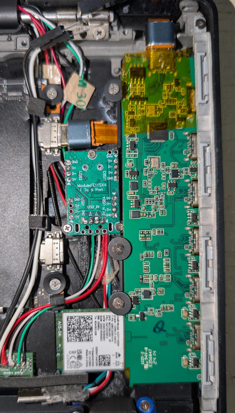
final look inside
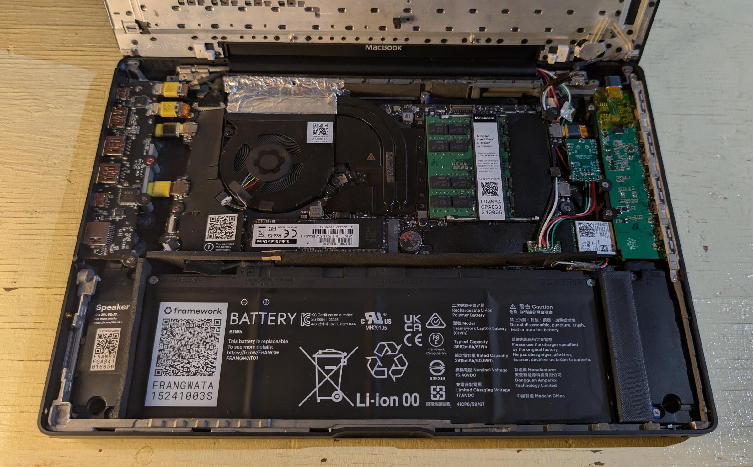
after finally getting everything to stay in place without snapping off, or possibly shorting everything, this is what the final look inside my framebook looks like.i added some padding around the battery to discourage hot air around the battery, as well as 3d printing that big rectangle to fill in some space.
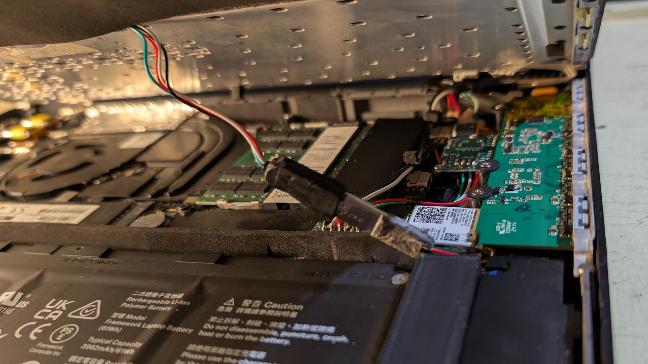
the wifi card managed to snuggly fit under the right usb hub, with the antennas running up to the right side of the top chassis.to connect the top case i added a male usb c port to the usb module to connect to the top case's soldered on female usb c port.the reason why i did it like this is so that way if i disconnect the top case from the framebook, i can use any regular usb c m2m cable to use the top case anywhere i want.
gallery & conclusion


overall this was a really fun and interesting project. from start to finish this took me around 3 months. i learned alot from this project, from how to solder, how to 3d model, this was a really nice way to learn these skills.there are somethings i would've like to have done better or differently, namely making some custom pcbs in place of my usb hubs so i could have any i/o i want, and finding a better way to mount stuff instead of super glue lol.
thanks for reading all the way through about my amateur attempt at "retrofitting" my macbook! sorry if i glossed over or skipped some stuff, i didn't really properly document things or even take photos along the way, most of this article is just me recollecting what i did in, semi-chronological order.
if you do have questions about my process, shoot me an email or dm me on bluesky.
i do have some very special thanks for some people that made this whole thing possible:N3rding for sending me the input shim for the top case and power buttonMy friend Phillip for teaching me how to use blender to make my lil standoffs and the i/o shield.and YOU, for reading this lil blog, article, thing, whatever !!! :P
